Tuesday, April 10, 2012
It’s a NERD thing..
Last night I did something I have not done in a very long time – pulled an All-Nighter. Kristi was a bit lonely last night, but stopped checking on me after about an hour. And as time went on, it was almost 0400 (4:00am) when I checked to see ‘How Late It Was’. Might as well keep going. A TRUE All-Nighter! Only the True Nerd can know the rush of chasing down details, having them point to another are of change. Moving to it, and solving that one. Then there is that other thing I thought of while doing this prior thing.... Ya, Nerd Nirvana!
See, I had downloaded KiCAD and was playing with it. Running through a couple of step-by-step examples to see how the whole schematic to PCB layout tools integrate. Have to admit, this was all new to me. Though I have designed a few circuits in my day (well, ‘back in the day’ more like) I used a drafting board and pencils. Then we sent it out to a house to have the PCB laid out. Unless it was a small one, in which case I busted out the light box, Mylar, and the Stick-on things! Oh What fun!
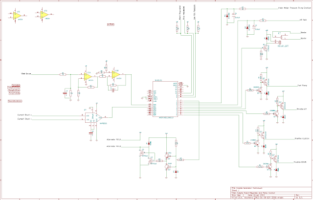
As last night progressed I started putting down the basis for the Kubota alternator regulator I have been thinking about. One to be based on an Arduino Uno micro-controller. Over the past weeks I have collected potential solutions for the various parts. How does one read the Amp shunt, want to be able to sense temperature of not only the battery but the motor for fault shut down. And did you know there are some not too common best practices behind reading the volts of an alternator? It involves syncing with the armature!!!
Well, here is what I ended up with today. What I call a ruff framework for the controller. It does not have the DC power supplies in, many of the circuits are value-less as I need to finalize what frequency I will be using for the field drive and adjust RC filters. There are also some additional filters that can go into the Amp shunt circuit, need to dig into that. Plus overall ESD hardening and protection. AND I need to go back and see if the snippets I pulled over the past few weeks actually will work and/or are efficient designs…
I also need to re-assign the pin outs into the Arduino controller – last night I just ran a wire to the nearest Analog or Digital pin, without regard to if those pins can actually produce a PWM signal, or accept an interrupt. Just Analog or Digital, no level of detail beyond that.
But though I would put up what I have. Next few weeks I will tackle the above issue, and then decide where to go with this play-thing.
Subscribe to:
Post Comments (Atom)


No comments:
Post a Comment
Note: Only a member of this blog may post a comment.